
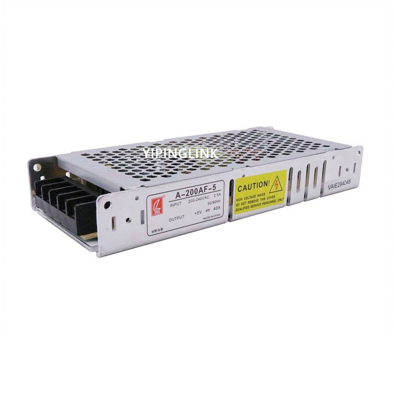
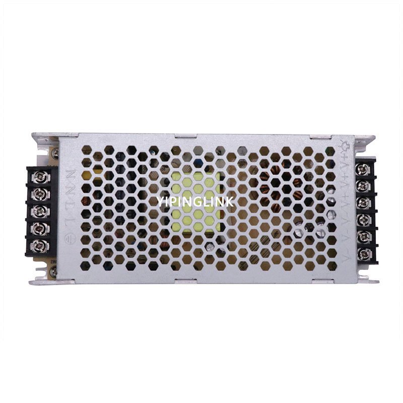
⬤Standard slim model,height 30mm ⬤20~+70C working temperature (refer to derating curve) ⬤Protections: short circuit/overload ⬤100% full load burn-in test ⬤High efficiency, High reliability ⬤2 years warrantyA-200AF-5X3 is Led display power supply without fans. The input voltage rang is 176~264VAC and output voltages are 2.8V、3.3V、3.8V、4.2V、4.5V、5V. It can be applied to Led display、LED indicator light and other Led display fileds. This series product is ultra-thin design, with a height of only 30mm, and can adapt to a variety of box size requirements. Super high efficiency, compact shell design and good heat dissipation ensure the long-term stable work of this series of products.
|
Model |
A-200AF-2.8X3 | A-200AF-3.3X3 | A-200AF-3.8X3 | A-200AF-4.2X3 | A-200AF-4.5X3 | A-200AF-5X3 | |
|
Input |
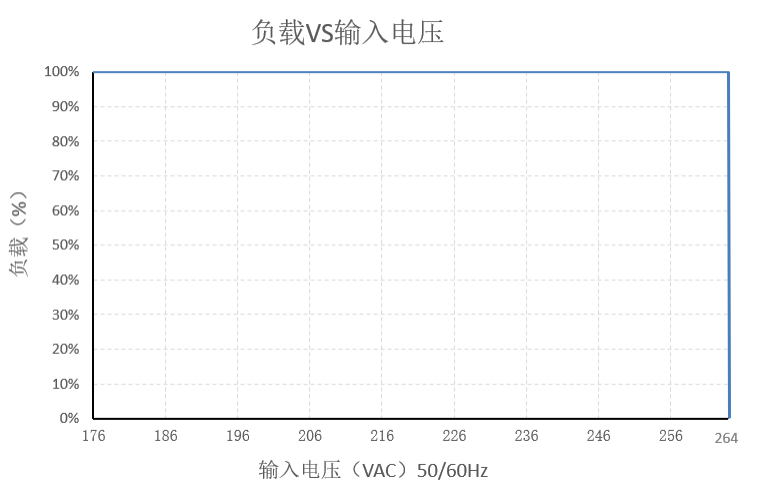
Voltage range |
176~264VAC |
|||||
|
Input current |
230VAC/2.5A |
||||||
|
Efficiency |
≥81% |
≥82% |
≥83% |
≥84% |
≥85% |
≥86% |
|
|
Frequency range |
47~63HZ |
||||||
|
Leakage current |
<3.5mA/240VAC |
||||||
|
Inrush current |
60A/230VAC |
||||||
|
Output |
DC voltage |
2.8V |
3.3V |
3.8V |
4.2V |
4.5V |
5V |
|
|
Rated current |
40A |
40A |
40A |
40A |
40A |
40A |
|
|
Power |
112W |
32W |
152W |
160W |
180W |
200W |
|
|
Voltage adj.range |
/ |
/ |
/ |
/ |
/ |
/ |
|
|
Ripple and noise |
170mVp-p |
170mVp-p |
170mVp-p |
170mVp-p |
170mVp-p |
170mVp-p |
|
|
Set up,rise time |
2500ms,50ms/220VAC 100% load |
|||||
|
|
Hold up time |
10ms/220VAC 100% load |
|||||
|
|
Line regulation |
±0.5% |
±0.5% |
±0.5% |
±0.5% |
±0.5% |
±0.5% |
|
|
Load regulation |
± 1.0% |
± 1.0% |
± 1.0% |
± 1.0% |
± 1.0% |
± 1.0% |
|
|
Output Voltage Accuracy |
±3.0% |
±3.0% |
±3.0% |
±3.0% |
±3.0% |
±3.0% |
|
EMC |
EMS |
Design refer to:EN55024 ;EN61000-4-2,3,4,5,6,8,11 |
|||||
|
|
Harmonic current |
Design refer to:GB17625.1;EN61000-3-2,-3 |
|||||
|
|
EMC |
Design refer to:EN55022,Class A |
|||||
|
Safety |
Safety standard |
Design refer to:GB4943/UL1012 |
|||||
|
Withstand voltage |
I/P-O/P:3KVac/10mA; I/P-CASE:1.5KVac/10mA; O/P-CASE:0.5KVAC/10mA each testing time:1min |
||||||
|
Isolation resistance |
I/P-O/P: 50M ohms; I/P-Case:50M ohms; O/P-Case:50M ohms |
||||||
|
Protecti on |
Over Voltage |
||||||
|
|
Over load |
110~165% rated Hiccup mode, recovers automatically after fault condition is removed | |||||
|
|
Over Temperature |
/ |
|||||
|
|
Short circuit |
Power supply protection after short circuit, and output can be recovered automatically after eliminating short circuit | |||||
|
Envirome nt |
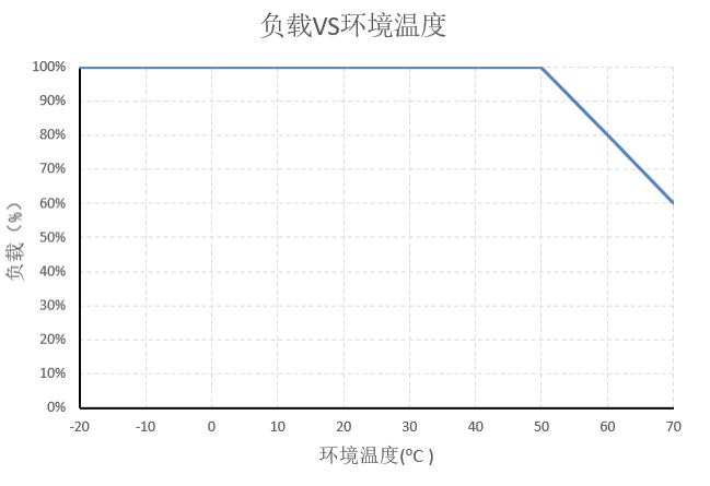
Working temperature and humidity |
-20~70℃; 20%~95%RH no condensing (refer to derating curve) | |||||
|
Storage temperature and humidity |
-30℃~85℃; 10%~95%RH nomondensing | ||||||
|
Vibration |
Frequency range 10 ~ 500Hz,acceleration 2G, each sweep cycle for 10min, 6 sweep cycles along X, y, Z axis | ||||||
|
Shock |
Acceleration: 20g, duration: 11ms, 3 impacts along X, y, Z axis | ||||||
|
Altitude |
2000mtrs (for every 100 m higher than 2000 m, the ambient temperature decreases by 0.6 ℃) | ||||||
|
Reliability |
MTBF |
25℃:250000Hrs, MIL-217 Method | |||||
|
Others |
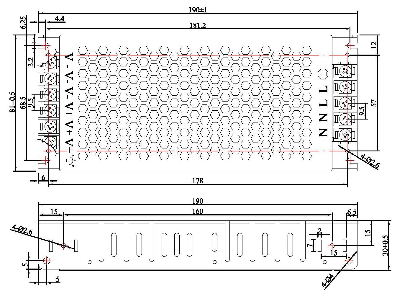
Size |
190*81*30 mm (L*W*H) | |||||
|
|
Packing |
0.36Kg/piece,30pieces/carton,11KG/carton | |||||
|
|
Cooling mode |
☑ Free air □ Fan | |||||
|
|
Extension mode |
three proofings ☑ terminal cover □ Low temperature start (-40℃) others | |||||
|
Remarks |
*In order to extend the lifetime, it is recommended to configure the load more than 30% of the remainingallowance. For example: the power of the device requires 100W, then use the power of not less than 130W. *Ripple test method: 20MHz oscilloscope in power output terminal test, oscilloscope probe wire length is not more than 12mm, and input parallel 47uF electrolytic capacitors and 0.1uF high frequency capacitance probe. *All electrical performance tests are performed at 25 C. *When the product is used in full load, the aluminum plate with an area of 400 * 400 * 3mm shall be added for auxiliary heat dissipation. *The power supply is a part of the components of the equipment system. All EMC tests are conducted by installing the sample on the metal plate. The power supply shall be confirmed with the terminal equipment for electromagnetic compatibility. | ||||||